Monday, May 26, 2014

5/19 post


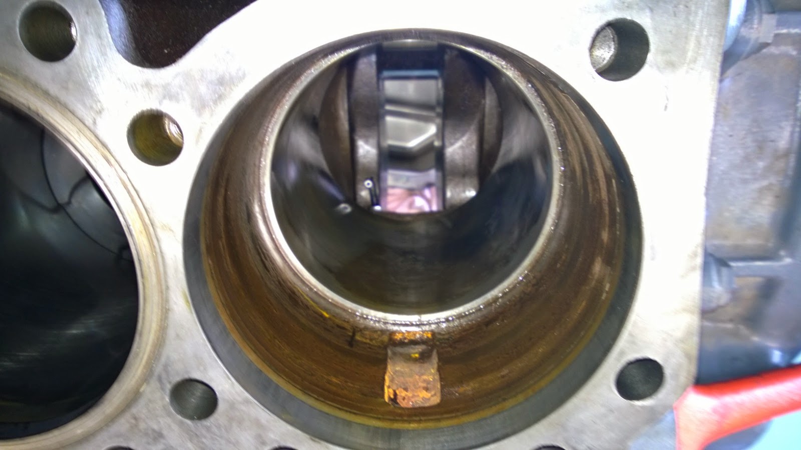
We've disassembled our Mack engine and taken out a piston and cylinder liner. Everything went well but when we tried to take the cylinder liner out we ended up cracking it. As you can see in the picture the bore tapers and we had a puller that fit on the top of the liner but not the bottom. After we heard it crack (which didn't take much by the way) we stopped and tried to figure out what went wrong. The liner actually needed a custom puller made for it that Jeff had fabricated. We also had some trouble getting out the injectors because we didn't know that you had to slide out the rest of the fuel system first.
Piston with the fire rings to the left.
Look at the rust on these passages from sitting.

Our cracked cylinder liner.

Our piston before removing from the engine. The rings lying on top are called "fire rings"


Bore for the cylinder liner.


Bore tapers so the bottom is actually smaller than the top.


Piston, rod, rodcap, and cap bolts on the table.


Our head off the engine with the valves still inside of it. The headgasket is lying on top.

Exhaust side with the gaskets still on. Look at the heat marks on the studs. That's how hot this gets.

3516 Disassembly

One thing I learned from taking apart the 3516 is that the manual is written by engineers. They often instruct you to take apart every single piece of a component possible when in reality you can just take off an entire unit leaving many components intact. For example the throttle linkage can come out as a complete unit versus disassembling every fastener which is tedious and impractical whilst it is still inside the engine.

At first it seems really daunting to take apart an engine that's this size. After using the manual and slowly taking it apart I realized it's like any other engine with similar components. The only difference is it's giant sized and the head requires an overhead crane to move to a workbench. Taking out the piston took a little bit of finesse. I ended up using the handle of a plastic sledge to push it out until the seals broke but took care not to launch it out the garage door. The J nozzle must be removed first before you can do that though otherwise you could damage it.

I found that bagging components and fasteners with like parts was very helpful in staying organized. It's very easy to start mixing up components and it's worth the time it takes to compartmentalize everything. The electric impact was very useful in removing all the many fasteners except for the head bolts. That required a much larger air powered impact.

Head with the valves and lifters inside.
Valve springs still installed. They require a special tool for removal.
It collapses the springs so you can remove the retainers.


Piston is an articulating piston. Here it is attached to
the connecting rod and the piston pin is next to it.

Piston with piston pin ande bearing cap with bearing installed.


Monday, May 12, 2014

5/12 blog


11)      Charge air cooler outlet
22)      (IMT) Intake manifold temperature sensor
33)      LP Boost/LP Temp sensor
44)      (MAF) Mass airflow sensor
55)      Humidity Sensor/Air inlet Temperature Sensor (AIT)
66)      (O2S) Oxygen Sensor
77)      (EGRT) Exhaust Gas Recirculation Temperature Sensor
88)      (IMP) Intake Manifold Pressure Sensor
s
1
11) Injector (6 of them)
22) Fuel Rail
33) Fuel Rail Pressure Limiting Valve
44) Fuel Return from Cylinder Head
55) Engine Fuel Return Connection (to chassis filter)
66) Fuel Supply to DSI unit
77) Fuel Return Line
88) Fuel Filter Assembly
99) Drain Screw
110) Fuel Delivery Pressure Sensor
111) Fuel Primer Pump Assembly
112) LP Fuel Pump
113) HP Fuel Pump
114) (FRP) Fuel Rail Pressure Sensor
115) ?

Cold Start Assist System
e1) (CSFI) Cold Start Fuel Igniter
22) (CSFS) Cold Start Fuel Solenoid valve
33) (CSR) Cold Start Relay


Wednesday, May 7, 2014

1st week of Diesel Engines

One valuable piece of information I learned was about the Craknshaft Position Sensor. It tells the computer the exact position and RPM of the crank shaft. This allows the computer to control the timing and lets it know whether to advance or retard it. Another thing I've learned is when taking off a head you take the bolts out a certain way. Same goes for when you're torquing down the headbolts. You want to do it in the correct order so that the headgasket is compressed evenly.


For our engine we chose the straight six Mack engine.

We begin to disassemble the top of our engine.


Jeff continued his failure analysis. The conclusion that he came to was the balancing shaft broke which led to catastrophic failure.